Sonde Tracker³ is a portable radiosonde tracking device I built using off-the-shelf components. It features a 3D printed 1U CubeSat frame which is the actual size of numerous CubeSat satellites currently orbiting the Earth. The frame is highly customizable. Below I describe just one of several configurations I considered during the design process (another configuration uses 2-3 SDRs to track multiple radiosondes but eliminates the power bank).
Components
Universal 1U CubeSat – https://www.thingiverse.com/thing:4096437
Nylon Hex Spacer Standoff Kit – https://www.amzn.com/B07TP2YYQB
Raspberry Pi 4 Model B – https://www.raspberrypi.com/products/raspberry-pi-4-model-b/
GT-U7 GPS Receiver – https://www.amzn.com/B07P8YMVNT
RTL-SDR Blog V3 Dongle and Antenna Kit- https://www.rtl-sdr.com/buy-rtl-sdr-dvb-t-dongles/
403MHz Filtered Preamp – https://store.uputronics.com/index.php?route=product/product&product_id=54
10,000mAH Power Bank – https://www.amzn.com/B08L3CC222
6-inch USB 2.0 Male to Female Extension Plug – https://www.amzn.com/B01GA1GKYW
6-inch Micro USB Cable – https://www.amzn.com/B094Q9TKZR
6-inch SMA Male to SMA Male RG316 Coaxial Jumper Cable – https://www.amzn.com/B08DG7JFV7
Software
radiosonde_auto_rx – https://github.com/projecthorus/radiosonde_auto_rx
Chasemapper – https://github.com/projecthorus/chasemapper
gpsd – https://gpsd.gitlab.io/gpsd/
Assembly
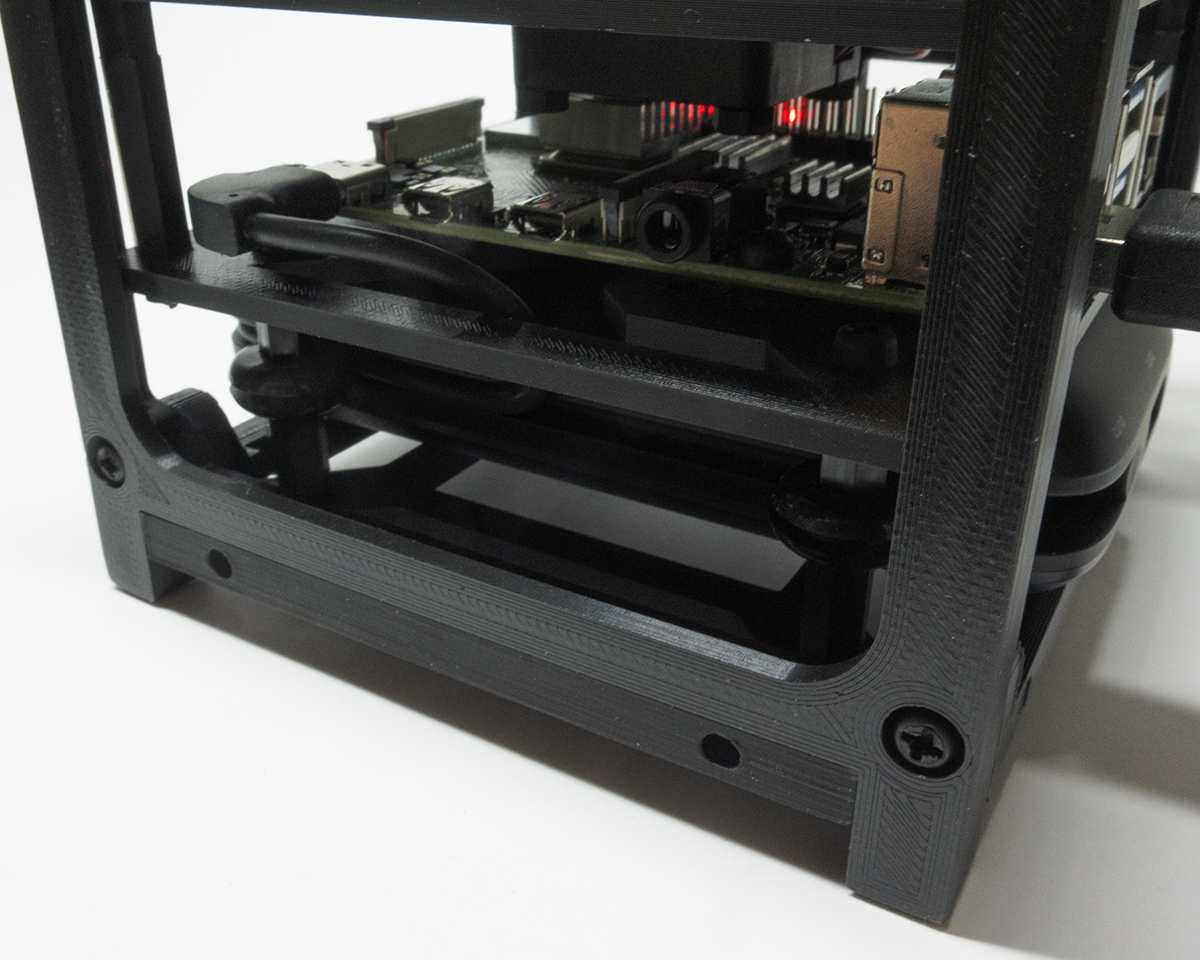
The Pi is attached to a CubeSat Adaptor Mount using nylon hex nuts as standoffs. This platform is then attached to a CubeSat Bottom Frame using 27.5mm nylon standoffs (15mm + 10mm + hex nut). This provides the clearance needed for the power bank. I also placed some rubber grommets on the 27.5mm standoffs to keep the power bank securely in the frame. Above the Pi is another CubeSat Adaptor Mount that is attached using 26mm nylon spacers (20mm + 6mm). This mount has been modified so a 25mm fan can be attached from below.
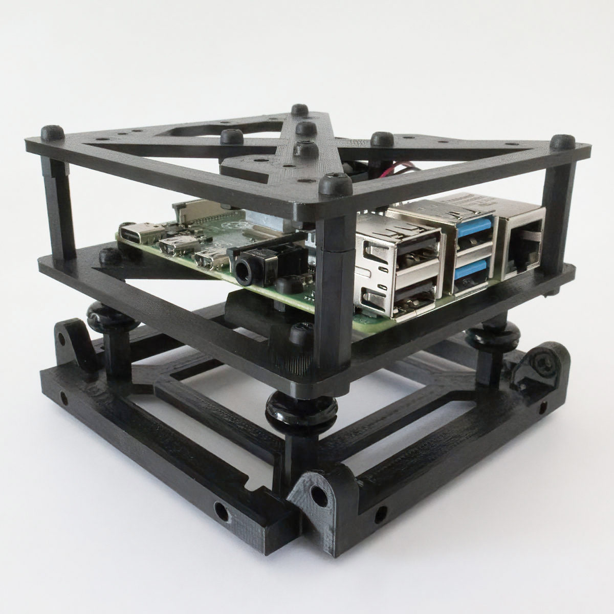
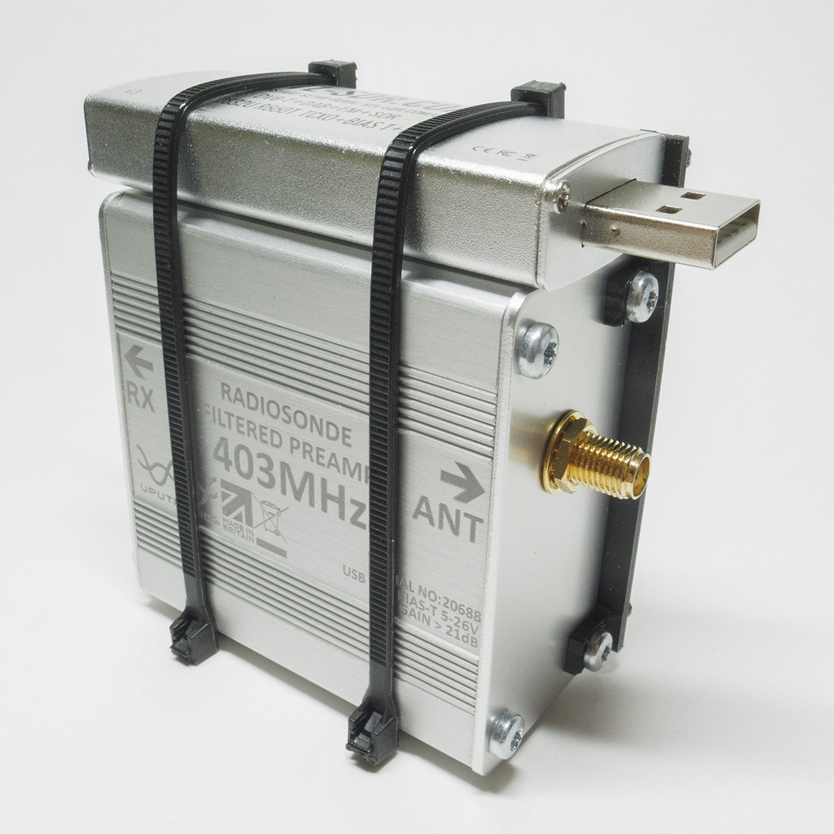
Attached to the top of the fan mount are the SDR and preamp.
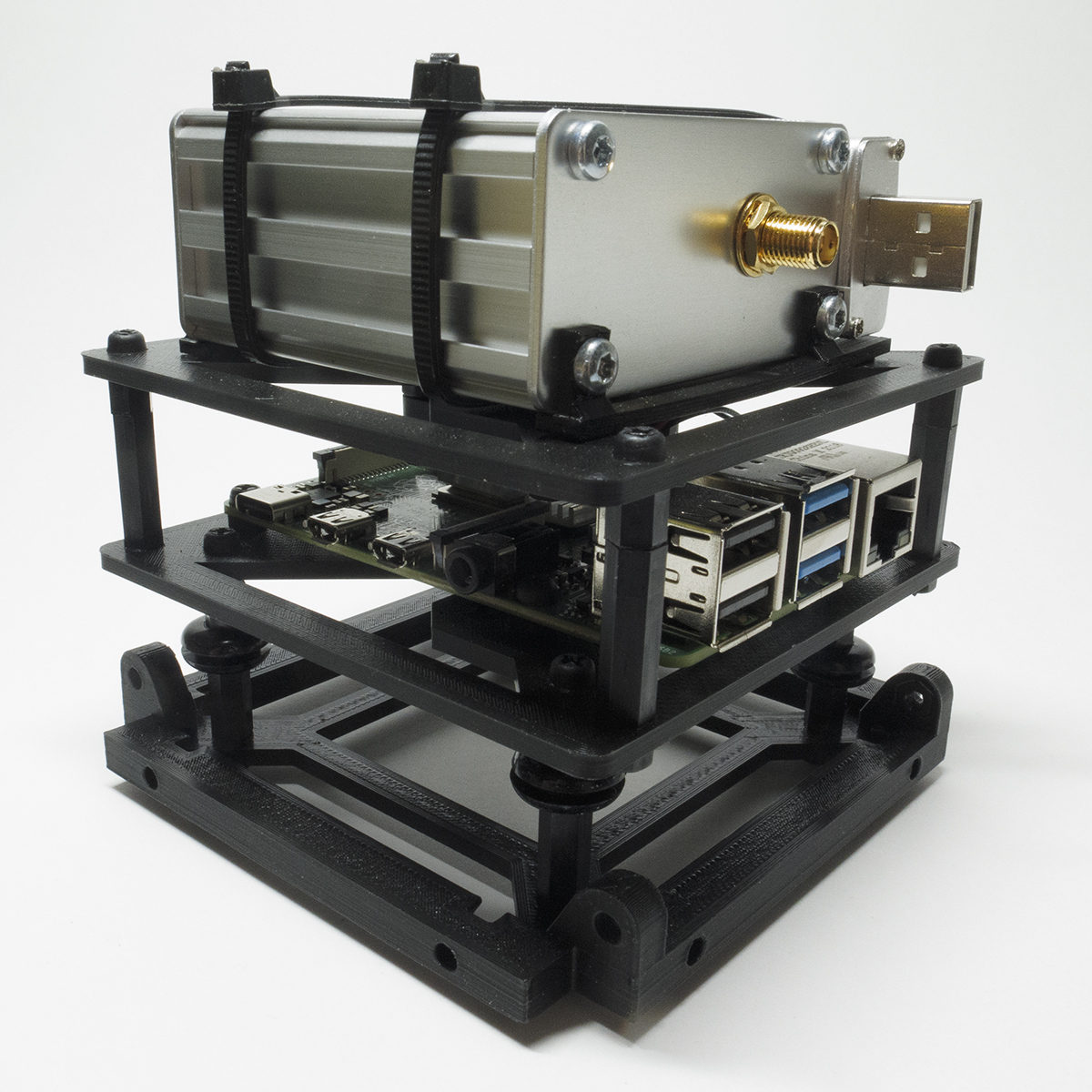
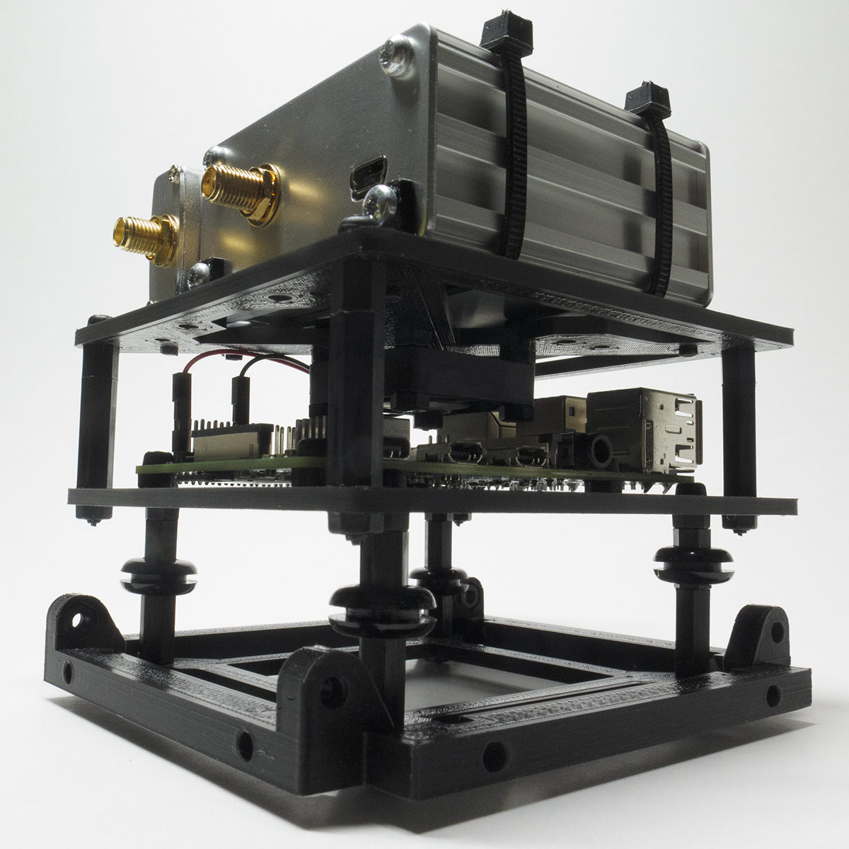
Next the rest of the frame, consisting of two CubeSat Side Frames and another CubeSat Bottom Frame, is connected to the existing CubeSat Bottom Frame using nylon 12mm screws and hex nuts. I modified one of the side frames to hold the GT-U7 GPS receiver. I also modified the additional bottom frame (which now becomes the top frame) to hold the GPS patch antenna.
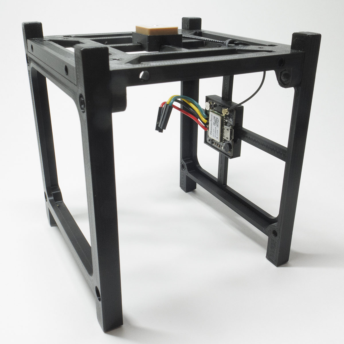
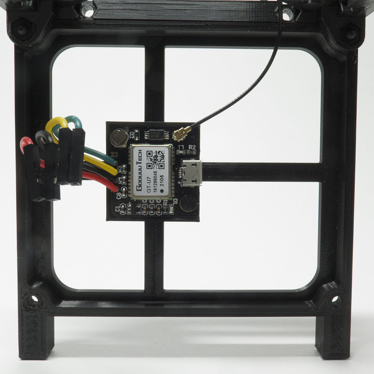
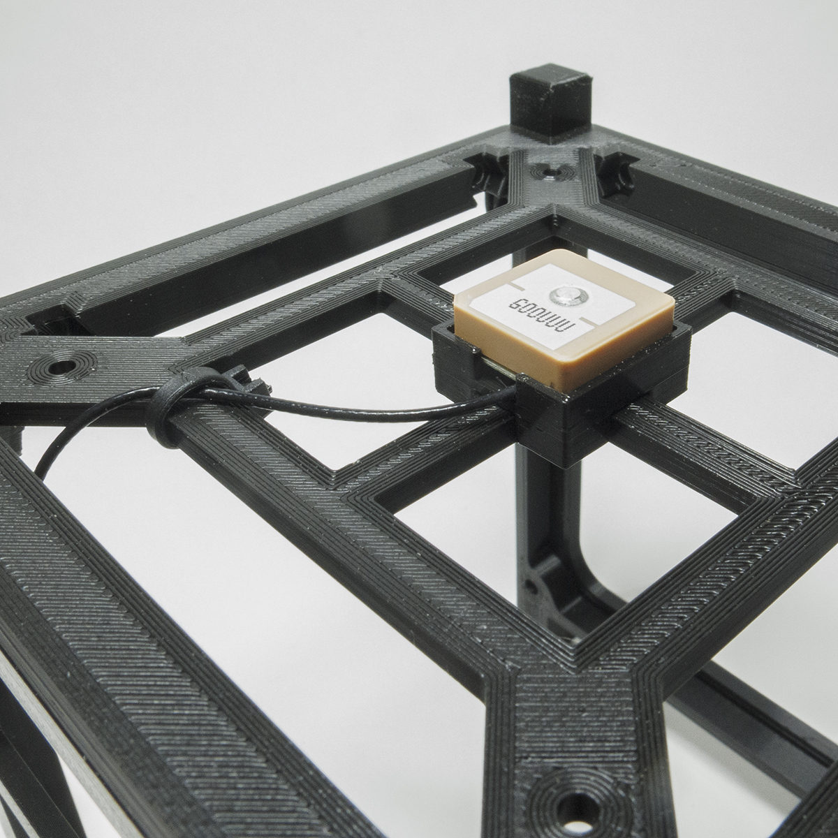
The equipment interconnects are pretty straightforward.
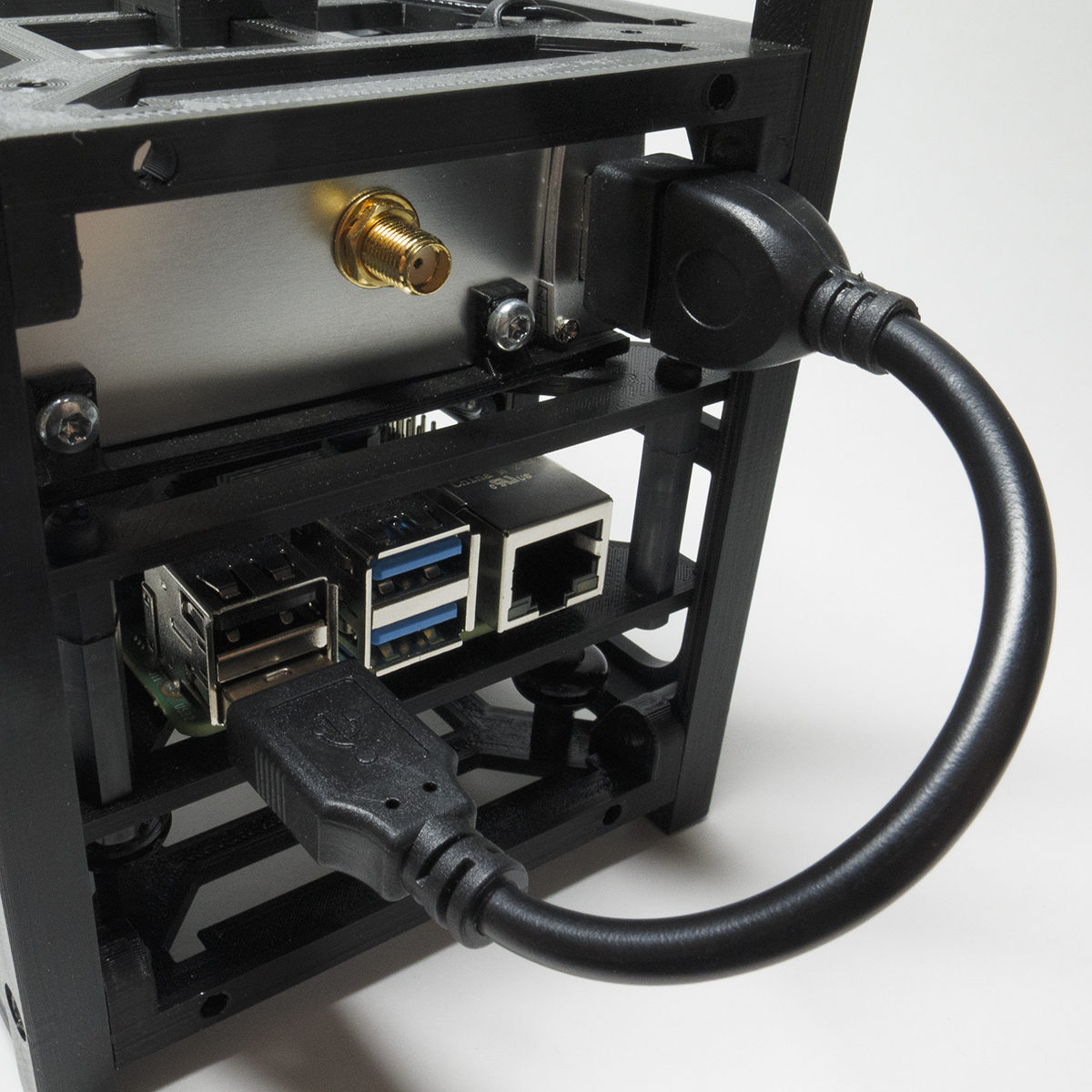
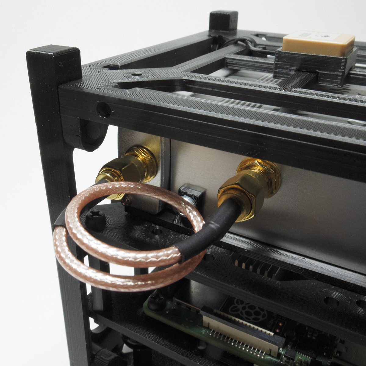
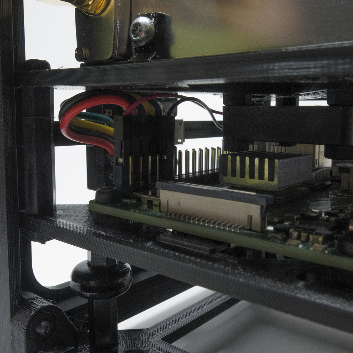
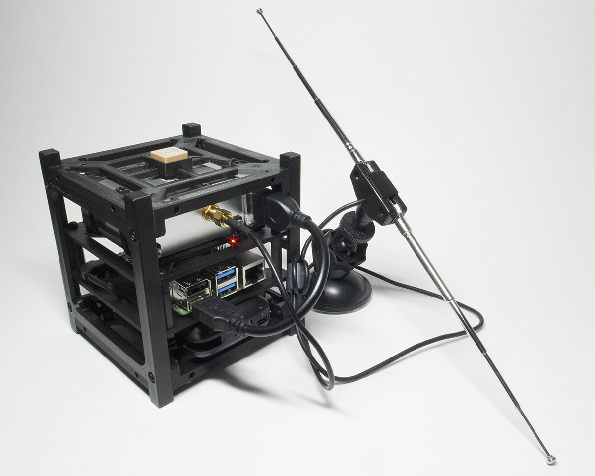
Finally, the 10,000mAH Power Bank slides firmly into the space at the bottom of the cube. It provides enough power for extended morning and evening chases. I also chose this power bank because it has an integrated USB-C power cord.
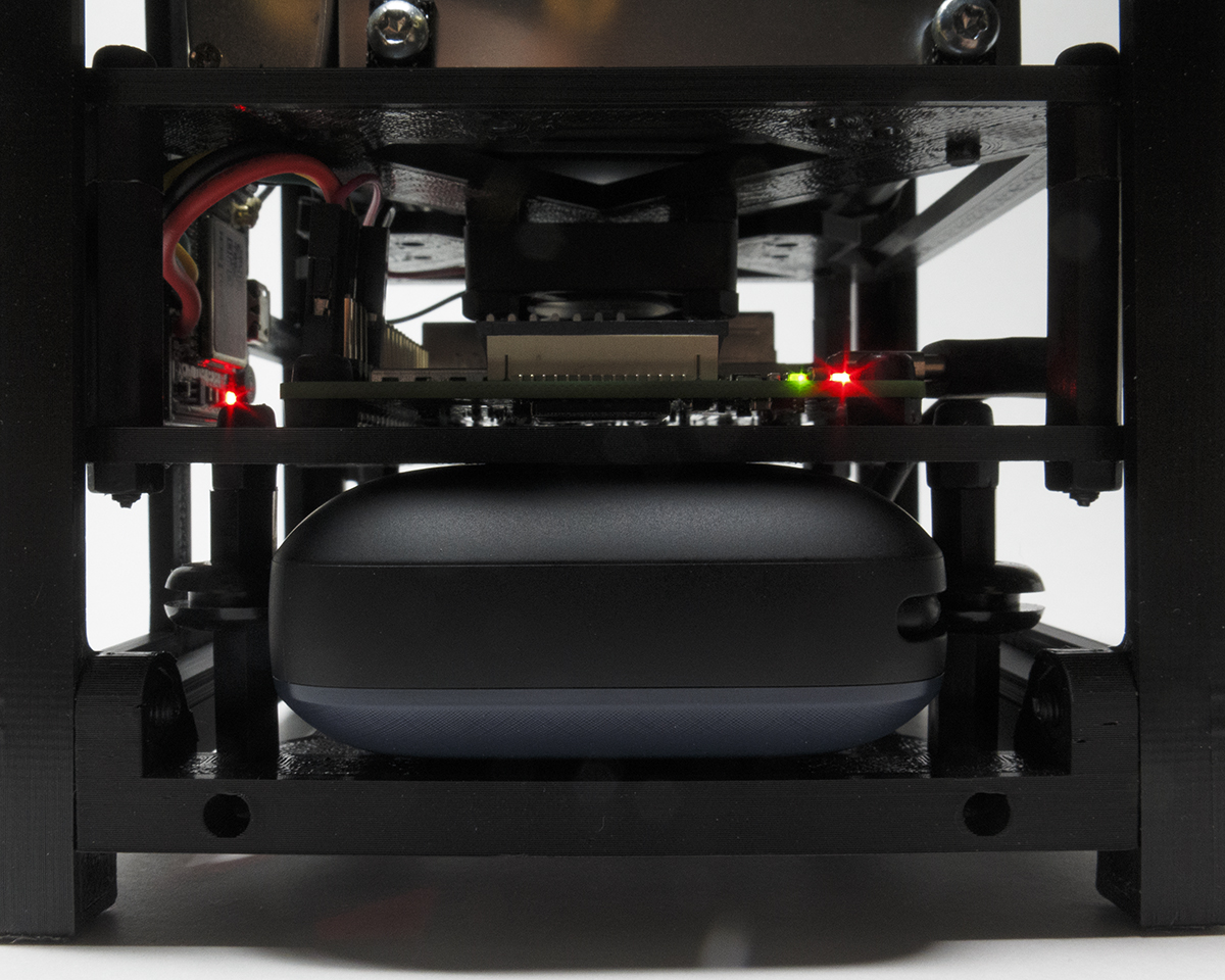
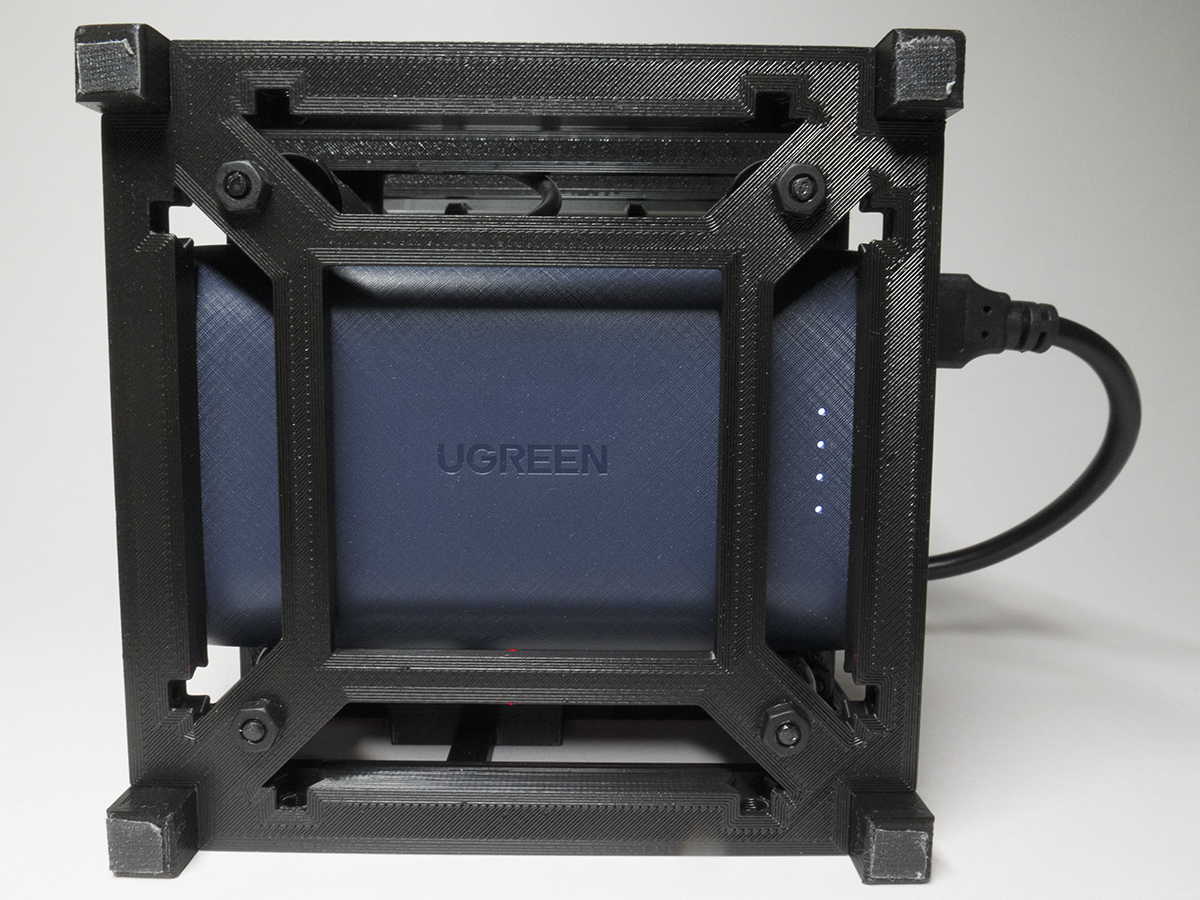
I have attached some gaffers tape to the bottom legs to keep it from sliding around.
Usage
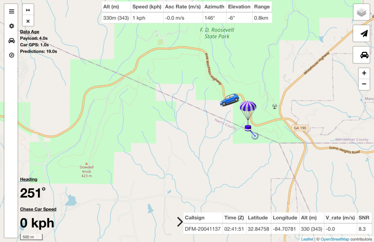
The software uses the WiFi hotspot on my phone for the data connection (should a data connection not be available the software can still function using offline maps). I then use a tablet to connect to a couple webpages that are hosted on the Pi. The first page is Chasemapper which is the primary display used during a chase. It displays the location of the radiosonde and your vehicle. It also provides range and bearing information so you can hopefully track down and recover the radiosonde.
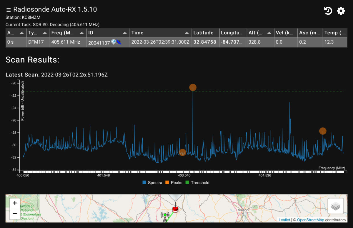
The other webpage is the radiosonde_auto_rx status page. This shows the location of the radiosonde and a scan plot of the frequency range that is being searched. This page also allows you to look at and download historical track data.
Here is what the system looks like set up in my vehicle.
There is no radiosonde visible on the screen because it had stopped transmitting by the time I arrived on site (you can read about it here).
